As part of the VarioPore project, the Deigner working group will produce nanopores using electroporation and test their suitability for nanopore-based diagnostics using electroion beams. Nanopores will be chemically surface-modified for this purpose. Cultivated B. burgdorferi and its characteristic molecules such as surface proteins and antibodies are used as test objects. Finally, the measurement results will be compared with clinical samples and compared using PCR analyses and ELISA.
Done by Prof. Maurizio Gullo from University of Applied Sciences Northwestern Switzerland
Real-time movie captured from the 2PP 3D printer showing the fabrication process of a 3D cage structure. The structural filaments of both the cage and the integrated alignment marks are approximately 1 µm in thickness. As with other 2PP images, no scale bars are included in this visualization.
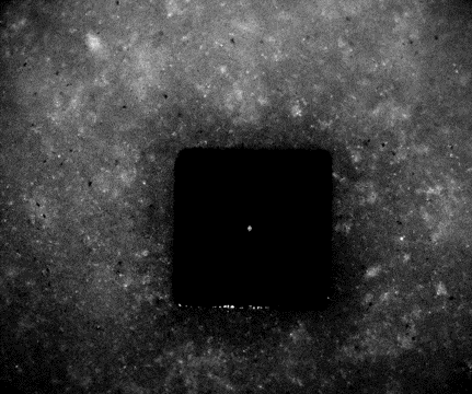
Snapshot from the two-photon polymerization (2PP) 3D printer utilizing backside illumination. The prominent black square (200 × 200 µm²) serves as the alignment mark. Centrally located is a silicon nitride (SiN) membrane containing a nanopore approximately 8–10 µm in diameter. Overlaid on this is a thinner, transparent polyethylene glycol diacrylate (PEGDA) membrane, approximately 2 µm thick, featuring a smaller pore with a diameter of ~0.8–1 µm. Note that scale bars are absent in these 2PP printer images.
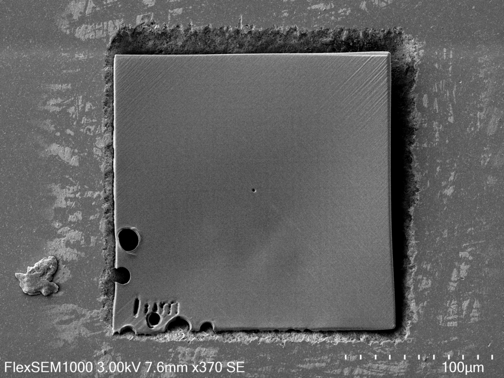
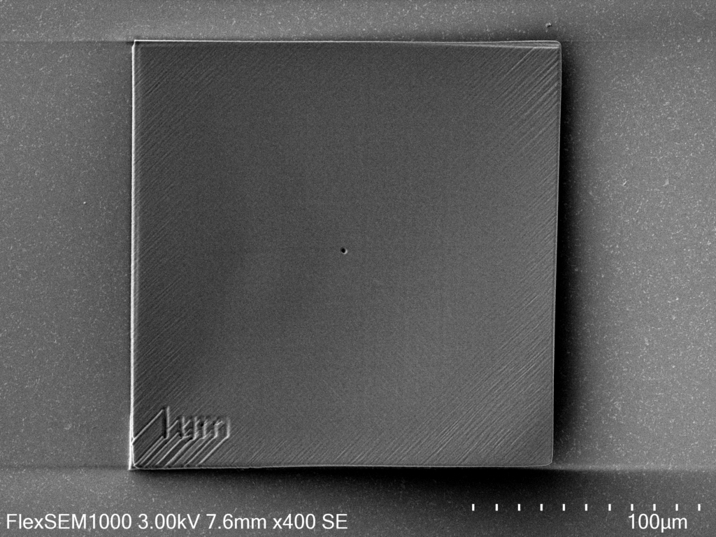
Scanning electron microscope (SEM) image of the PEGDA membrane positioned within the engraved alignment square. The crater-like features observed in the bottom-left corner are artifacts caused by localized overheating or micro-explosions, likely resulting from impurities present during the laser-based 3D printing process.
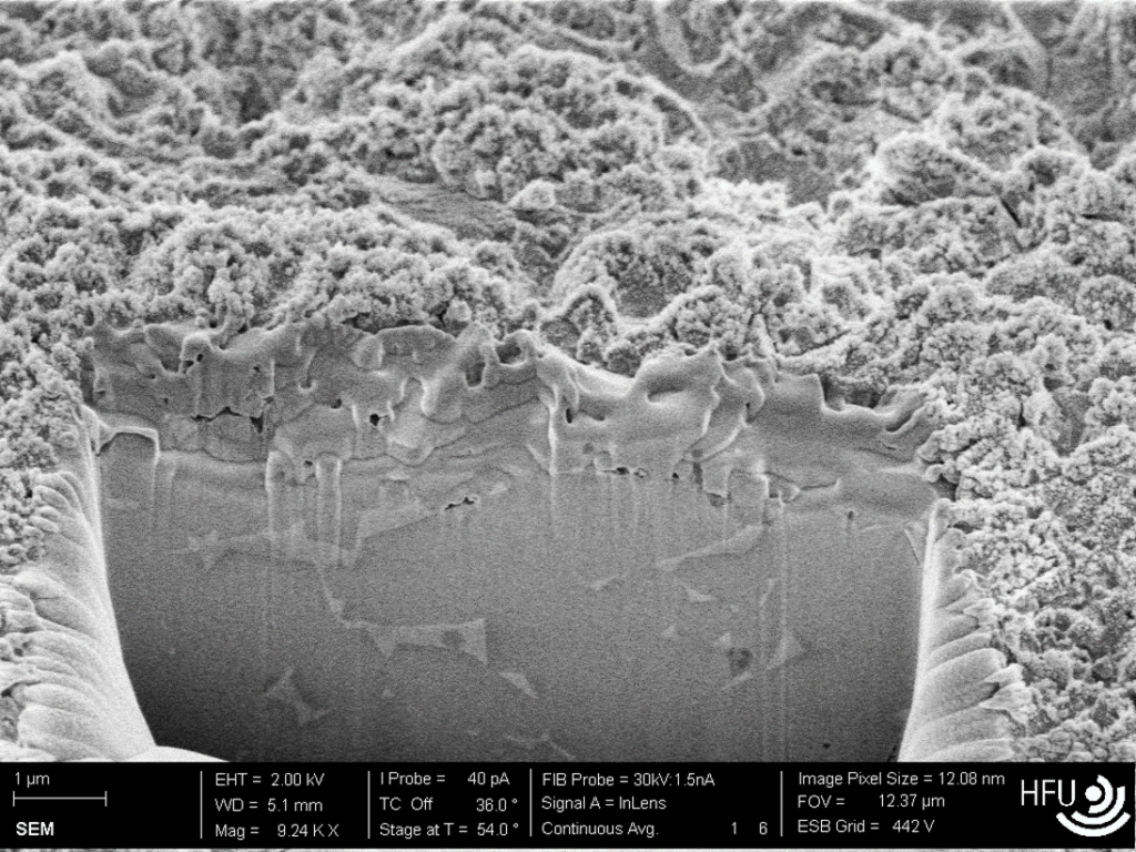
Zoomed-in SEM image of the membrane aperture shown in Figure 2, highlighting the smaller pore of ~0.8–1 µm in diameter. While the outer diameter of the aperture matches the original design specifications, the inner diameter is typically reduced by 20–30% due to proximity effects and diffusion limitations during the development stage of the fabrication process.
SEM image of a PEGDA membrane fabricated on the flat side of the chip, illustrating a defect-free structure. No signs of thermal damage or material degradation due to laser-induced overheating are visible in this configuration.
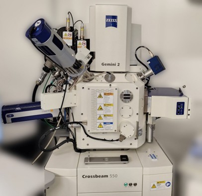
To evaluate the surface quality and microstructural characteristics of the processed samples, scanning electron microscopy (SEM) was employed. The SEM analysis was performed using a ZEISS Crossbeam 550 system, which enabled high-resolution imaging of the nanopore structures and their surrounding areas. As shown in the image, the SEM provided detailed cross-sectional views, allowing precise assessment of surface morphology, layer integrity, and possible material redeposition effects. This characterization was essential for validating the processing parameters and guiding further optimization steps.
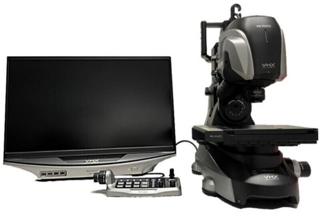
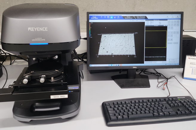
Visual inspection and dimensional control of the samples were carried out using a high-resolution digital light microscope. The Keyence VHX system, shown in the image, was used to precisely measure and document the geometry of the fabricated structures. This method allowed for non-destructive evaluation of the surface features and ensured that the produced diaphragms met the required dimensional specifications. The combination of visual inspection and optical measurement played a crucial role in the iterative optimization of the laser processing parameters.
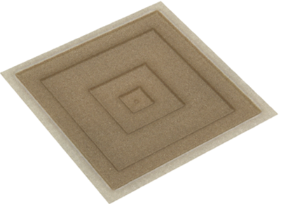
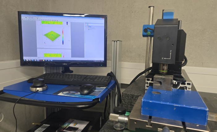
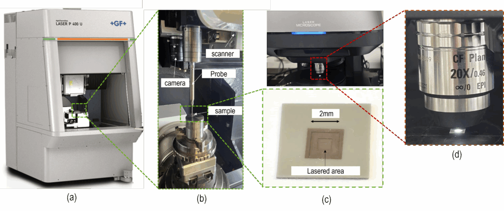
Confocal microscopy was employed to evaluate the surface morphology of the fabricated samples in greater detail. This technique allowed for high-resolution, three-dimensional imaging of the sample surfaces, providing precise information on surface texture, depth profiles, and topographical variations. By capturing optical slices at different depths, confocal microscopy enabled accurate reconstruction of the surface structure, which was essential for assessing the quality and uniformity of the laser-processed areas. The data obtained supported the refinement of processing parameters and helped ensure consistency across different samples.
The first samples were successfully developed and distributed to all project partners for evaluation. Through daily communication and regular online meetings, feedback was collected and discussed collaboratively. Based on this continuous exchange, the final dimensions of the initial diaphragms were refined and agreed upon, ensuring that they met the technical requirements and expectations of all involved groups.